
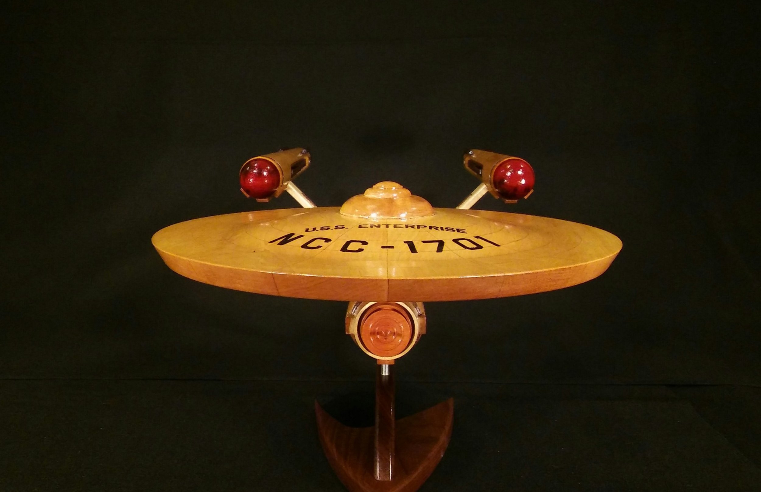


This page details the step by step construction of a 36 inch model of the Starship USS Enterprise from the original Star Trek series. The theme of this project is to use all natural wood grain with no paint. The colors are accomplished by incorporating different woods of various colors.
The Original Studio Model
Shown below are images of the ship from the 1960's TV show and the original studio model, currently displayed at the Smithsonian National Air and Space Museum in Washington, DC. The model is 11 feet long.


Schematics
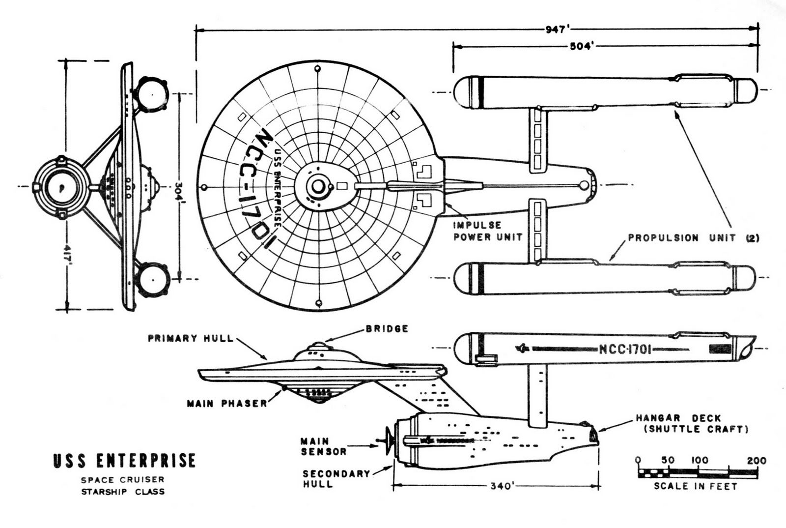
To create this model, the original print created for the studio model designed by Matt Jefferies was used. Incidentally, according to Jefferies, the registry number NCC-1701 signified "Naval Construction Contract of the first vessel of the seventeenth starship design of Starfleet."
Major Components
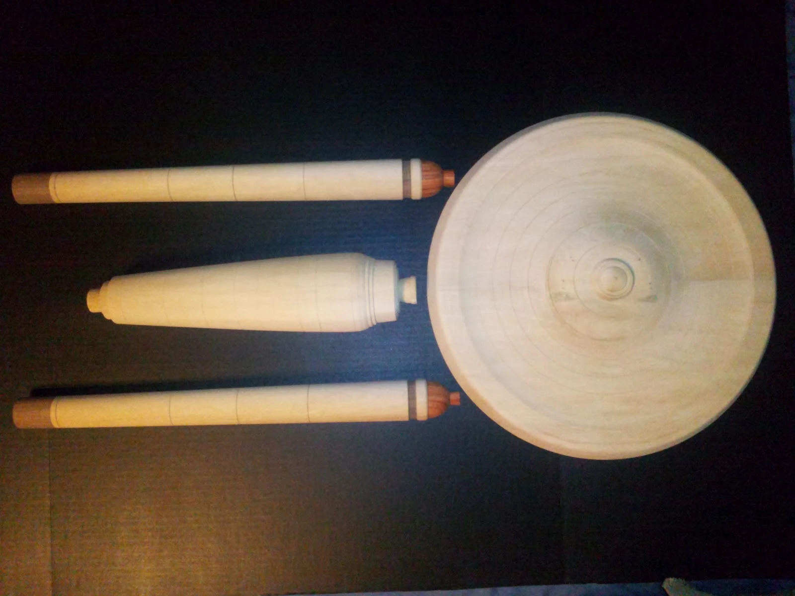
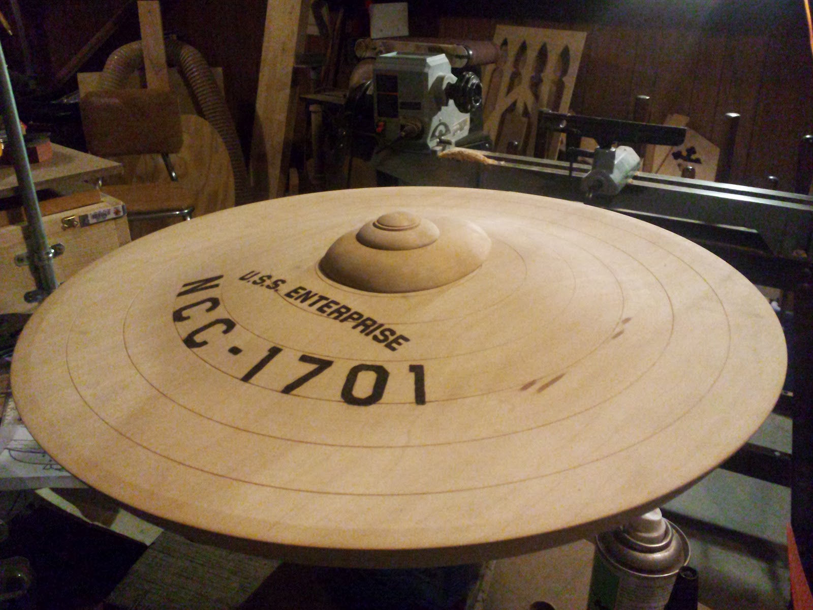
The main hull is made of maple. All major components were turned on a wood lathe. The saucer is 16 inches in diameter. The warp engines are made of maple as well, with black walnut and padauk pieces glued together.
Saucer Section
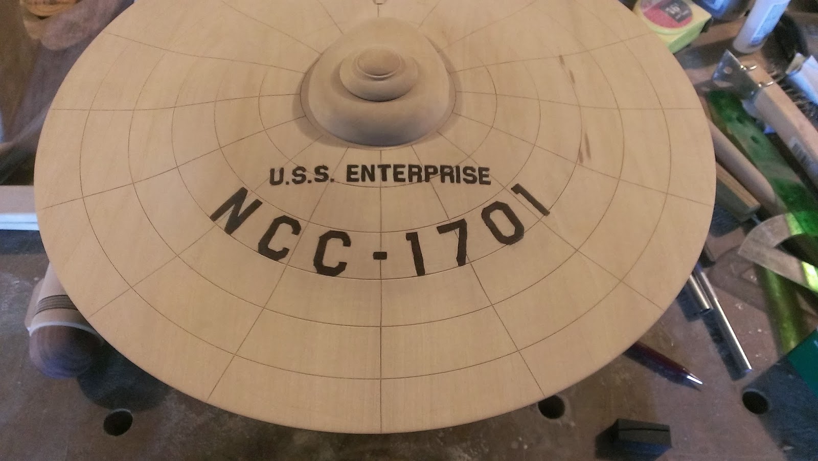
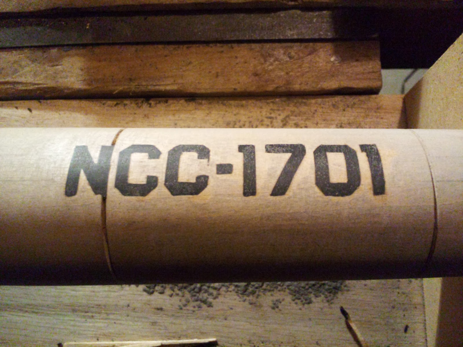
The ship's registry number was transferred to the wood using carbon paper. Then, the letters were carved out using a rotary tool to a depth of 1/16" - 1/8". Superglue and ebony sawdust were pressed into the indentations and sanded flush with the surface.
The base for the bridge was cut on a band saw. The side profile was cut first, then the top profile. Finally, the curvature was defined using a wood rasp and sanded smooth. The bridge was turned on the lathe.
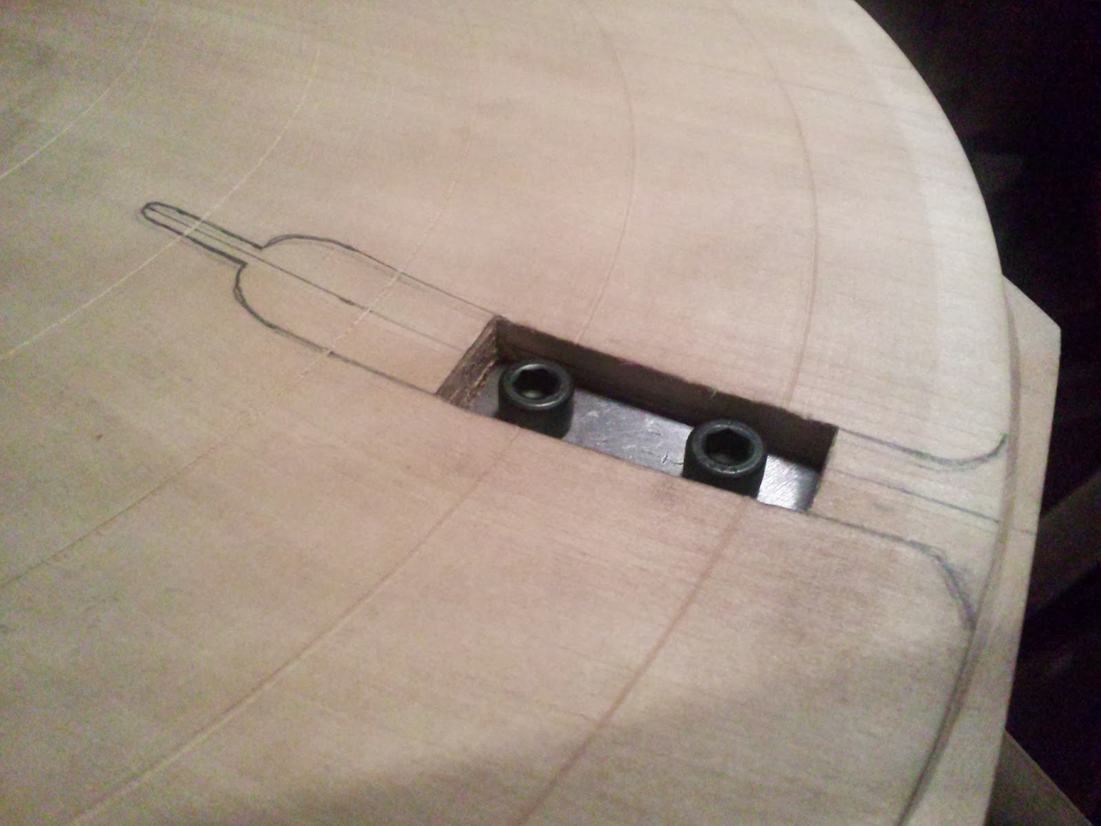
The neck was planed down to 3/4" thick and cut on the band saw. The edges were defined with a wood rasp and sanded smooth. Brass insets were inserted into the neck to secure it to the saucer. a rectangular washer was made to keep the wood from being damaged when the screws were torqued. The screws are appropriately hidden by the spine of the impulse engine.
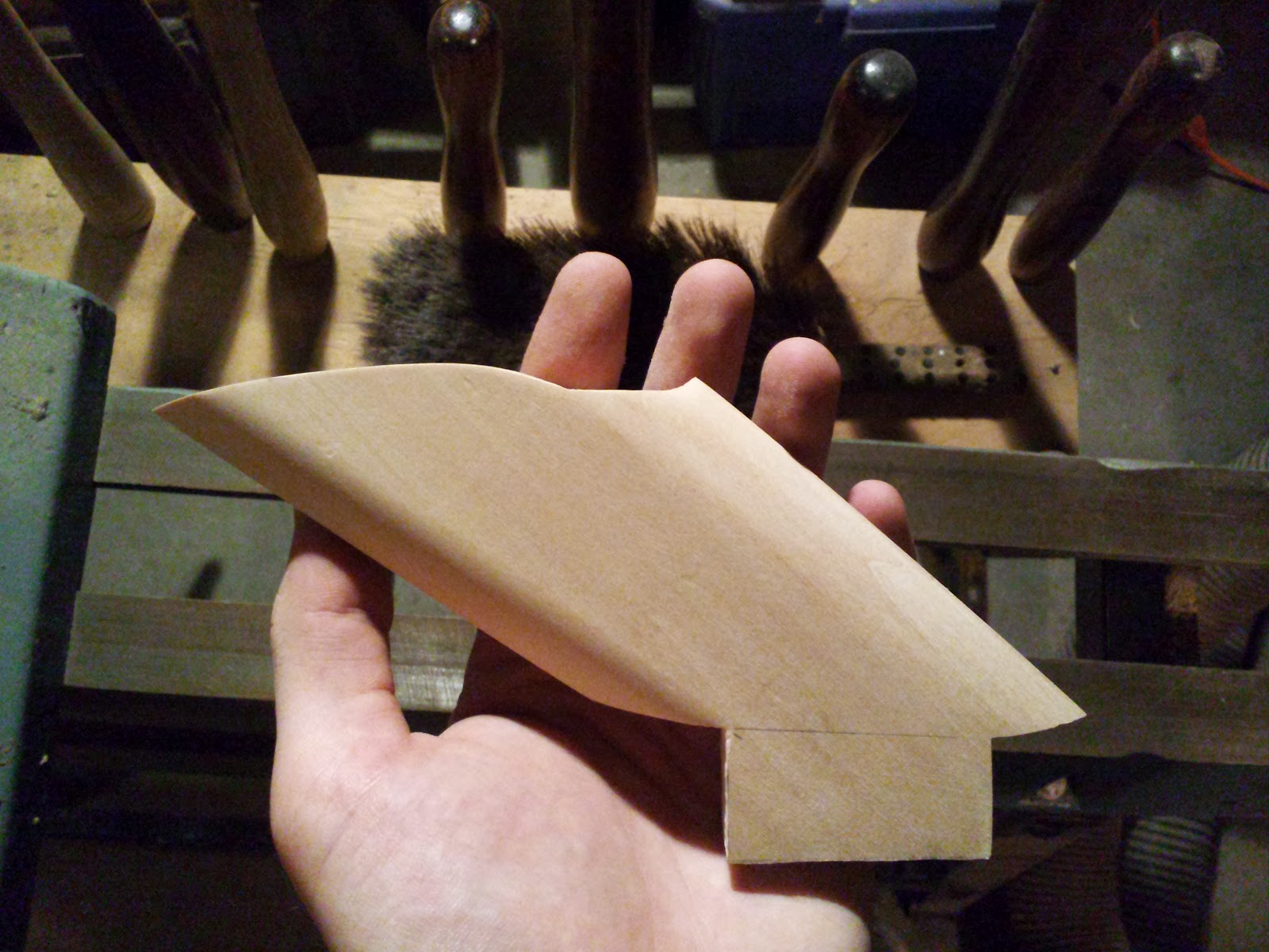
The impulse engine was cut on the band saw at the proper angle to mate with the edge of the saucer. The final shape was achieved using a wood rasp and sanded smooth. The exhaust vents of the engine were created using the superglue/sawdust technique with ebony.
Finally, the paneling marks were made using a chip carving knife.


Secondary Hull
The shuttlebay was carved out, creating a lip 3/32" thick. The clam shell doors were turned on the lathe and trimmed to mate inside the niche. The separation marks on the doors were made with a chip carving knife.
The beacon was turned on the lathe and the hole was drilled out. The countersink was carved, not drilled, to prevent the wood from being chewed up.
The base for the deflector dish, and the dish itself was made of osage orange, to emulate the copper color of the studio model.
The pin striping is made of padauk and the small boomerang is made of yellow heart.


Warp Engine Nacelles
The slots used to mount the engines onto the support pylons were marked out at a 45 degree angle to the vertical. Guide holes were drilled to facilitate carving out the slots. A fixture was made to hold the engines such that the longitudinal axis is held parallel to the surface upon which it rests. This ensure that any hole drilled using the drill press will be perfectly perpendicular to the axis.
The s-curve on the aft end of the engines was cut using the bandsaw. The fixture ensured that the s-curves are also perpendicular to the axis. Spherical elements were turned on the lathe and cut on the bandsaw to match the s-curve on the aft end of the engines. A groove was carved along the insides of the engines are the attachment of a long slender piece of black walnut.
Small elements were made of maple and black walnut were added to the engines to give greater detail.
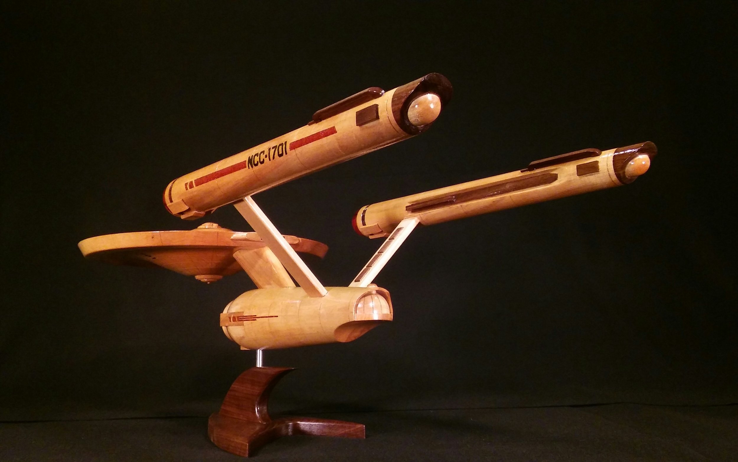
The registry number and pin striping were done using the superglue/sawdust method. The number is ebony, the stripe is padauk, and the boomerang is yellow heart.


Final Assembly and Base
The base is made of 1" thick black walnut. A 3/8" stainless steel rod is used to mount the ship to the base. The rod is 5" long and extends 2" into the model and 2" into the base. Stainless steel tubes are used inside the model and the base that fit snugly with the rod to eliminate wear between the rod and the wood. The shape of the base matches the design of the emblem on the uniforms of the original series. Finally, the model was coated five times with Minwax clear gloss polyurethane.


Construction Log
Day 1: Turned secondary hull; glued engine parts together and turned engines
Day 2: Turned saucer top and dremeled name and registry
Day 3: Name & registry inlaid on saucer top; saucer bottom turned
Day 4: Registry on saucer bottom dremeled and inlaid
Day 5: Bridge mount and bridge made
Day 6: Neck and impulse engine made
Day 7: Neck inserts installed; mounting [saucer-neck] holes drilled
Day 8: All slots cut (1 in each engine, 3 in secondary hull); engine struts made; aft section of secondary hull cut
Day 9: Hangar deck alcove carved, doors turned and scored
Day 10: Saucer-neck mounting point carved; square washer made; impulse engine spine made
Day 11: S-line cut in engines; inboard grooves carved
Day 12: Spherical pieces for engines made and installed; forward section of secondary hull turned and installed
Day 13: Deflector dish and base turned from osage orange and installed
Day 14: Hangar deck observation dome turned and installed
Day 15: Engine details made; Engine registries dremeled and inlaid
Day 16: Engine pin stripes and chevrons dremeled and inlaid
Day 17: Rectangular details for front section of secondary hull carved and installed
Day 18: Pin stripes on secondary hull dremeled and inlaid; rectangular details on engine struts made
Day 19: Radial lines scored into saucer; base made; final assembly
Day 20: Polyurethane coat